Electrical systems in vehicles rely on precise control, especially when it comes to managing power for lights, horns, fans, and other components. A relay plays a key role in this setup by allowing a small current to control a much larger one.
Among the different types available, the 5 pin relay stands out for its flexibility and wide range of applications. It is commonly used when a circuit needs both a normally open and normally closed path.
Working with a relay may look technical at first, but once the layout is clear, it becomes much easier to follow. Each pin has a specific role, and knowing how they connect can prevent wiring mistakes.
A proper setup ensures stable operation and protects the electrical system from overload. A clear understanding of the wiring structure allows anyone to approach installations with confidence and accuracy.
Table of Contents
Basics Of A 5 Pin Relay And How It Works
Structure And Purpose Of Each Pin
A 5 pin relay is designed with five terminals, each serving a distinct function. These pins are usually labeled as 85, 86, 30, 87, and 87a. The numbering may seem unusual at first, but it follows a standard used across automotive electrical systems.
Pins 85 and 86 are connected to the relay coil. When voltage is applied across these two pins, it creates a magnetic field that activates the relay. This action moves an internal switch, allowing current to flow through other terminals. One of these pins is typically connected to ground, while the other receives power from a control source.
Pin 30 acts as the common terminal. It is the main input for the power that will be distributed when the relay is activated. Pin 87 is the normally open terminal, meaning it only connects to pin 30 when the relay is energized. Pin 87a, on the other hand, is the normally closed terminal, which remains connected to pin 30 when the relay is not activated.
This design allows the relay to switch between two circuits. It can either connect power to a component when activated or disconnect it depending on the setup. The versatility of these connections makes the 5 pin relay suitable for a wide range of uses.
How The Switching Mechanism Operates
The operation of a 5 pin relay is based on a simple electromagnetic principle. When a small current flows through the coil between pins 85 and 86, it generates a magnetic field. This magnetic force pulls a metal arm inside the relay, changing the connection between the terminals.
In its default state, pin 30 is connected to pin 87a. This means power flows through the normally closed path. Once the relay is activated, the connection shifts from pin 87a to pin 87. This change redirects the current to a different circuit.
This switching action happens quickly and repeatedly without direct physical interaction from the user. It allows sensitive switches or control units to manage high-power devices without carrying the full electrical load.
Because of this mechanism, relays are often used to protect wiring and switches from excessive current. They ensure that high-demand components receive the power they need while keeping the control circuit safe and efficient.
Understanding The Wiring Diagram Layout
Reading The Standard Relay Diagram
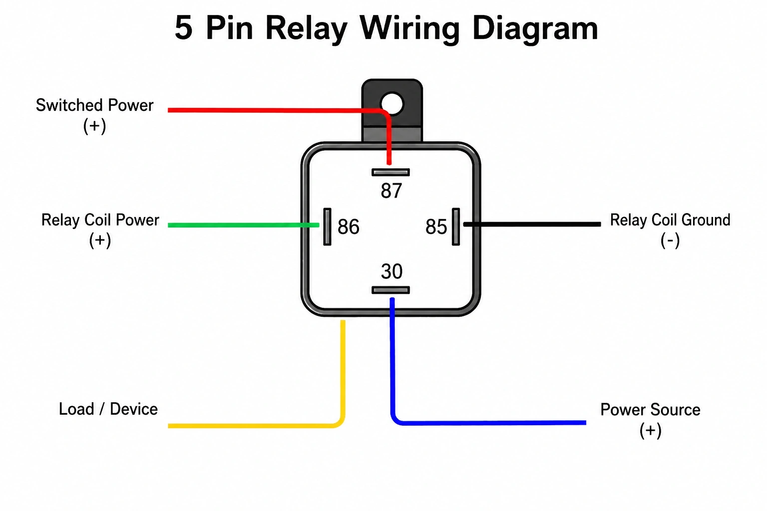
A wiring diagram for a 5 pin relay provides a visual representation of how each terminal connects within a circuit. It shows the relationship between the control side and the power side, making it easier to follow the flow of electricity.
The diagram typically separates the relay into two sections. One side represents the coil, connected through pins 85 and 86. The other side represents the switching contacts, including pins 30, 87, and 87a. This separation helps in identifying which part of the relay controls activation and which part handles power distribution.
Lines in the diagram indicate electrical connections. A straight line usually represents a wire, while symbols show components such as switches, batteries, or loads. Understanding these symbols is essential for accurate wiring.
The diagram also highlights the default position of the relay. It shows which pins are connected when the relay is not energized and how the connections change when it is activated. This information is crucial for setting up circuits correctly.
Careful reading of the diagram ensures that each connection is made in the right place. It reduces the risk of errors and helps in troubleshooting if something does not work as expected.
Common Wiring Configurations Explained
There are several ways to wire a 5 pin relay, depending on the intended use. One of the most common configurations involves using the relay to control a high-power device such as auxiliary lights. In this setup, pin 30 is connected to a power source, while pin 87 leads to the device. Pins 85 and 86 connect to a switch or control signal.
Another configuration uses the normally closed function. In this case, pin 30 is connected to pin 87a when the relay is inactive. This allows a device to remain powered until the relay is triggered, at which point the connection shifts to pin 87 and changes the circuit behavior.
Relays can also be used for switching between two different circuits. This is useful in applications where one function needs to be replaced by another when a condition is met. The relay acts as a bridge that redirects power as needed.
Each configuration serves a specific purpose. Choosing the right one depends on how the circuit is intended to operate. A clear plan before wiring helps ensure that the relay performs its role effectively.
Step By Step Guide To Wiring A 5 Pin Relay
Preparing Tools And Identifying Connections
Before starting the wiring process, gathering the right tools makes the task smoother. Basic tools such as wire strippers, connectors, and a multimeter help ensure accurate and secure connections. Using quality wires and connectors reduces the risk of electrical issues later.
Identifying each pin on the relay is the first step. The numbers are usually marked on the relay body, making it easier to match them with the wiring diagram. Confirming these labels prevents confusion during installation.
Planning the wiring path is also important. Deciding where each wire will run helps avoid clutter and ensures a clean setup. Keeping wires organized reduces the chance of accidental disconnections or short circuits.
Safety should always be a priority. Disconnecting the battery before starting work prevents accidental sparks or damage to components. Taking these precautions ensures a controlled and safe working environment.
Connecting The Relay In A Circuit
The wiring process begins with the power source. Pin 30 is connected to the positive terminal of the battery or another power supply. This wire often includes a fuse to protect the circuit from overload.
Next, pin 87 is connected to the device that needs power. This could be lights, a fan, or any other component. If the normally closed function is required, pin 87a is used instead.
Pins 85 and 86 are then connected to the control circuit. One of these pins goes to ground, while the other connects to a switch or control signal. When the switch is activated, it completes the circuit and energizes the relay.
After all connections are made, checking each wire ensures that everything is secure. Reconnecting the battery and testing the setup confirms that the relay operates as expected. A systematic approach helps achieve reliable results.
Practical Applications And Troubleshooting Tips
Real World Uses Of A 5 Pin Relay
A 5 pin relay is widely used in automotive systems because of its versatility. It can control high-power components such as headlights, fuel pumps, cooling fans, and horns. By using a relay, these devices can be operated without placing stress on switches or wiring.
Another common use is in security systems. Relays can interrupt or redirect power to prevent unauthorized use of a vehicle. They are also used in custom setups, such as adding aftermarket accessories that require controlled power distribution.
Relays are not limited to vehicles. They are also used in industrial equipment and home electrical systems where controlled switching is needed. Their ability to handle different configurations makes them suitable for a wide range of applications.
Understanding these uses helps in selecting the right relay setup. It also highlights the importance of proper wiring to ensure reliable operation.
Diagnosing And Fixing Wiring Issues
When a relay does not work as expected, troubleshooting becomes necessary. The first step is checking the power supply. Ensuring that pin 30 receives voltage confirms that the main input is functioning.
Next, the control circuit should be tested. Verifying that pins 85 and 86 receive the correct signals helps identify issues with switches or wiring. A multimeter can be used to measure voltage and continuity.
If the relay clicks but the device does not operate, the issue may lie in the connection between pins 30 and 87 or 87a. Inspecting these wires for damage or loose connections often reveals the problem.
In some cases, the relay itself may be faulty. Replacing it with a known working unit can confirm whether the issue is internal. Regular checks and proper installation reduce the likelihood of such problems.
Bottom Line
A 5 pin relay offers a reliable way to control electrical circuits with precision and safety. Its design allows for flexible configurations, making it suitable for a variety of applications. Knowing how each pin functions and how they connect ensures accurate wiring and dependable performance.
Careful planning, proper tools, and attention to detail make the installation process straightforward. A clear understanding of diagrams and configurations helps avoid common mistakes and simplifies troubleshooting.
Reliable electrical systems depend on correct connections and consistent operation. Taking the time to wire a relay properly ensures that it performs its role effectively and supports the overall performance of the system.

- How Long Does It Take For A Car To Cool Down Fully - May 1, 2026
- What Does DRL Mean On A Car And Why It Matters - May 1, 2026
- 5 Pin Relay Wiring Diagram Guide For Automotive Use - May 1, 2026