General Motors vehicles have used electric fuel pumps for decades, and those pumps rely on a small group of wires to deliver power, control signals, and fuel level information. When a truck or SUV refuses to start, stalls unexpectedly, or shows incorrect fuel gauge readings, the issue often traces back to the fuel pump circuit. At that point, identifying the correct wires becomes critical.
GM typically follows consistent wiring color conventions, but those colors can vary slightly by model year, platform, or engine configuration. Power feed wires, ground wires, fuel level sender wires, and sometimes fuel pump control module circuits are all bundled together in a single harness near the fuel tank.
Working with these wires requires accuracy. Misidentifying a ground as a signal wire or connecting power incorrectly can damage the pump or vehicle electronics. A clear breakdown of common GM fuel pump wire colors, their functions, and safe testing procedures prevents costly mistakes and ensures proper repair.
Table of Contents
Common GM Fuel Pump Wire Color Codes And Their Functions
Power Feed Wire Color And Role
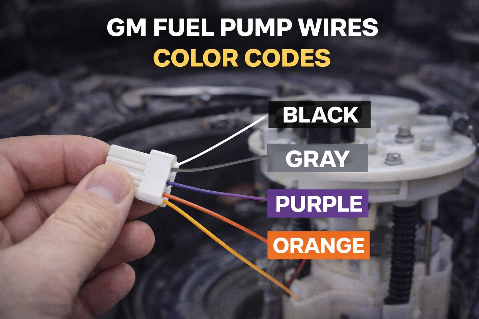
In many GM trucks and SUVs, the primary fuel pump power wire is typically gray. This wire carries 12-volt power from the fuel pump relay to the pump inside the tank. When the ignition is turned on, the relay briefly energizes the gray wire to prime the system. Once the engine starts, the engine control module maintains power to keep the pump running.
The gray wire is critical because it supplies direct voltage needed for fuel pressure generation. If this wire loses power due to corrosion, broken connections, or relay failure, the pump will not operate.
Testing the gray wire with a multimeter during key-on prime helps confirm whether voltage is reaching the pump connector. Consistent voltage indicates the upstream circuit is functioning properly.
Because it is the main feed wire, confirming its integrity is often the first diagnostic step in a no-start condition.
Ground Wire Color And Importance
Ground wires in GM fuel pump circuits are commonly black or black with a white stripe. The ground path completes the electrical circuit, allowing current to flow through the pump motor.
A poor ground connection can mimic a failing fuel pump. Even if the gray power wire shows full voltage, insufficient grounding will prevent proper pump operation. Corrosion near the frame rail or loose mounting bolts can interrupt the ground circuit.
Testing continuity between the ground wire and chassis metal ensures proper connection. Voltage drop testing while the pump is running provides a more accurate assessment of ground quality.
Reliable grounding is essential for consistent fuel pressure. Many intermittent fuel delivery problems trace back to weak ground connections rather than pump failure.
Fuel Level Sender Wire Colors
GM fuel pump modules also include wires for the fuel level sending unit. These wires commonly appear as purple, purple with white stripe, or tan depending on model year.
The sender uses variable resistance to communicate fuel level to the instrument cluster. Incorrect wiring or damaged sender circuits can cause inaccurate fuel gauge readings.
These wires do not carry pump power but transmit low-voltage signal data. Confusing sender wires with power wires during repair may result in gauge malfunction.
Careful identification prevents misconnection and protects the instrument cluster circuitry.
Variations Across GM Platforms And Model Years
Differences Between Older And Newer GM Trucks
Older GM trucks from the 1990s often used simpler four-wire configurations: gray for power, black for ground, purple for sender signal, and a second sender return wire.
Newer models, especially those with fuel pump control modules, may include additional wires. These systems regulate pump speed electronically rather than relying solely on relay activation.
Fuel pump control modules may introduce thicker gauge wires or additional signal circuits. Color patterns may still follow gray for power and black for ground, but confirmation through wiring diagrams is recommended.
Platform differences highlight the importance of referencing service manuals for specific year and model.
Impact Of Engine And Drivetrain Configuration
Different engine options within the same truck platform may include slight wiring variations. For example, heavy-duty models or performance variants may use upgraded fuel pump modules with modified harnesses.
All-wheel-drive or extended cab configurations may alter harness routing or connector placement. However, color coding typically remains consistent within production families.
Verifying connector pin positions and wire functions ensures accurate repair regardless of configuration differences.
Safe Testing Procedures For GM Fuel Pump Wires
Using A Multimeter To Check Power And Ground
Testing fuel pump wires safely begins with proper tools. A digital multimeter allows accurate voltage measurement without damaging circuits.
To test the gray power wire, set the meter to DC voltage and probe between the gray wire and ground during ignition prime. Voltage should briefly rise near battery voltage.
For ground testing, measure voltage drop between the black ground wire and chassis while the pump operates. Minimal voltage drop confirms a solid ground connection.
Avoid using test lights on sensitive circuits without confirming compatibility. Multimeters provide more reliable readings.
Back Probing Without Damaging Connectors
Back probing allows voltage testing without cutting or piercing wires. Using appropriate probe adapters protects connector seals and prevents future corrosion.
Cutting insulation to access wires should be a last resort and followed by proper sealing repair.
Maintaining harness integrity preserves long-term reliability and prevents future electrical faults.
Common Wiring Problems And Their Symptoms
Corroded Connectors Near The Fuel Tank
Fuel pump connectors are exposed to moisture, road salt, and debris. Over time, corrosion may develop on terminals, increasing resistance.
Symptoms may include intermittent stalling, hard starts, or pump noise without proper pressure output.
Inspecting connectors for green corrosion or loose pins identifies potential issues early.
Cleaning terminals and applying dielectric grease protects against future corrosion.
Melted Or Overheated Wiring
High resistance connections can generate heat. In some cases, fuel pump connectors may show signs of melting due to increased current draw.
This often occurs when a failing pump draws excessive amperage. Replacing the pump without repairing damaged wiring may result in repeat failure.
Inspecting both wiring and pump condition ensures complete repair.
Broken Harness Sections
Fuel pump harnesses may run along frame rails where they are vulnerable to physical damage. Debris impact or improper lifting techniques can damage wiring.
Broken wires may cause sudden no-start conditions or intermittent pump function.
Careful inspection along harness routing identifies physical damage.
Repairing with proper soldering and heat-shrink protection restores circuit integrity.
Best Practices For Fuel Pump Wiring Repairs
Use Correct Gauge Wiring For Repairs
Replacing damaged wires requires matching the original wire gauge. Undersized wire increases resistance and overheating risk.
Using automotive-grade wire ensures durability under vibration and heat exposure.
Maintaining factory specifications prevents electrical imbalance.
Secure Harness Routing Properly
After repair, ensure harnesses are clipped securely away from exhaust components or moving parts.
Improper routing can cause repeated damage.
Attention to detail during installation protects long-term reliability.
The Practical Perspective
GM fuel pump wire color codes generally follow consistent patterns, with gray for power, black for ground, and purple or tan for fuel level sender circuits. While these colors remain common across many platforms, variations exist depending on model year and configuration.
Accurate identification is critical when diagnosing no-start issues or replacing fuel pump assemblies. Testing voltage and ground integrity with proper tools ensures reliable diagnosis. Avoid guessing wire functions based solely on appearance without confirmation.
Electrical repairs demand precision. Matching wire gauge, protecting connectors, and maintaining secure routing preserve system performance. With correct identification and careful testing, fuel pump wiring issues can be resolved effectively while preventing further complications.

- How Families in UAE Manage Changing Vehicle Needs - March 4, 2026
- How Many Axles On A Car And What They Do - March 2, 2026
- Metal Shavings In Oil Causes And What It Means - March 2, 2026